Showing posts with label Notebook. Show all posts

Mar 3, 2023

Asus ExpertBook : Essential Information

 Asus ExpertBook 14 (B1400C)

Model : B1400CEAEY


1) To enter into BIOS --> Press --> [F2]

2) Once inside BIOS, to disable the "Secure Boot" function --> Press --> Advanced Mode [F7]

3) At Advanced Mode page, browse to --> Security --> Secure Boot --> Select --> Disabled

4) To Save & Exit --> Press --> [F10]

5) Press [F2] again at next restart, to select boot device --> Press --> Boot Menu [F8]

6) Select your boot device and press --> [ENTER]


A) Special Functions only available for Asus ExpertBook model is the "Calculator Mode" at the TouchPad, to enable this, the Asus TouchPad drivers must be installed. And to enabled the calculator mode display, just double-tap on the top-right corner.

B) To only enable direct "Fn" keys at keyboard (eg. [F1] to [F12] keys), just need to press --> [Fn] + [ESC] keys together once, then the "Fn" key will works directly.

C) To disable built-in touchpad when an external mouse is connected, under Windows --> Start --> Settings --> Devices --> Touchpad --> Disabled/Untick = Leave touchpad on when mouse is connected.


!!! HAPPY COMPUTING !!!


Mar 20, 2020

Notebook : Acer Switch Keyboard Dock (Disassembly)

Been a while since my last post, been bog down with tons of work in the new company.

Recently my colleague asked my help to upgrade his Keyboard Dock with an SSD and below are my findings.

1. From first glance, this seems simple enough as most of the screws is visible at the bottom.


2. After removing those visible screws, I find it difficult to remove until I noticed the long rubber strips.


3. Upon removing the rubber strip there lies 2 more hidden screws.


4. And voila, the bottom cover is now removed revealing the components.


5. Removing the HDD is relatively simple but you need to be careful to disconnect the HDD's connector on the board itself first.


6. The HDD is just a SATA-2 port thus replacing it with a SATA-2 SSD is very simple and straight-forward.

7. As always, removing the back cover requires patients and do not force it as this will damaged the clips. As we all knows aged plastics tends to breaks easily and thus using the correct tools is always important.


!!! HAPPY COMPUTING !!!

Jul 1, 2019

Notebook : HP Beats 15-p016AU (Disassembly)

This is another example of bad design of notebook, you need to disassemble almost all the parts just for a simple HDD and RAM upgrades.

Let's start shall we....

1. Remove all the screws as shown.


2. You need to remove the black cover to reveal another hidden screws.


3. Next turn over the notebook with the keyboard facing you and slowly open the entire bezel, becareful on the keyboard & touchpad's ribbon cables.


4. After removing the bezel, you can now see the mainboard as shown below. If you have noticed, the RAM slots are not visible.


5. Disconnect all ribbon cables and cables and remove the screws as shown below.


6. Slowly remove the mainboard, as always do not force it out. Once the mainboard is removed, turn it over and now you can see the RAM slots (as shown below).


You know I don't really understand by manufacturer decided not to grant easy access to these components... I really don't... anyway I hope these will help others.

!!! HAPPY COMPUTING !!!

Jun 27, 2019

Notebook : Lenovo IdeaPad 305-15IBD [MT : 80NJ] (Disassembly)


Another posting for disassembly of a Lenovo notebook, the access to the RAM and HDD upgrade is very simple but to service the CPU's fan or refreshing the thermal compound required further steps as below :-

1. Remove the easy access cover, screws position as highlighted with arrow.


2. After removed, it will reveals the RAM slots and the HDD. Even access to the CMOS battery and the Wireless card is visible.

At this stage you can easily upgrade the RAM or the HDD but if you wanted further access such as to the CPU then proceed to step #3 below.


3. Remove those screws as per highlighted in arrow below.


4. Turn over to remove the keyboard panel.


5. Carefully and slowly peel the keyboard panel to reveal the bezel. Becareful of the keyboard's ribbon cable as usual.

As this unit was serviced before, thus I did noticed some missing screws which was supposed to be there but aren't. As such I was unable to determined the actual screws location for this bezel.


6. Now slowly and carefully remove the keyboard's bezel for the mainboard access.


7. Next is to disconnect those ribbon cables as circled in red and remove the screws as per arrows shown below.


8. Once you have done that, slowly flip over the mainboard to access the CPU's heatsink and fan, there you can proceed to refresh the thermal compound and clean the heatsink and fan.

This model is very easy and have simple access, you just need to be very meticulous in looking for the screws as its very obvious and noticeable.


!!! HAPPY COMPUTING !!!

May 4, 2019

Notebook : Lenovo IdeaPad S500 [P/N : 500-14ISK] (Disassembly)

For this particular model the Lenovo IdeaPad S500 is kinda also like the rest, where you need to remove the entire bottom cover just for RAM or HDD upgrade. Luckily it was relatively easy (so to speak) to locate the DIMM slot(s).

But sadly there is only 1 DIMM slot available thus you can only upgrade to a higher capacity RAM instead of adding more.

As I'm removing the bottom cover, I found out that there's are no hidden screws beneath those rubber pads. Well... lucky me.   :D


Immediately I'm greeted by the mainboard, HDD and battery..... but wait, where is the RAM's slot(s) ? Not another type that need to remove the mainboard just to flip over to reveal the it ?


Of course no, its just been covered up by the aluminium shielding (as show below).


After removing the shielding, now you can see the DIMM slot is now visible.


Sadly as I've mentioned earlier, there is only a single DIMM slot available. So you can only choose to replace the existing RAM with higher capacity. Upon checking with Kingston website, only the following model is available :-

1) Kingston 8GB DDR3 1600Mhz [P/N : KCP3L16SD8/8]

There is also a 4GB model, but the existing unit is already at 4GB capacity thus I never bother to check it out since higher capacity of 8GB is available.

This also shows that the maximum capacity available for this notebook is max out at 8GB, there's no way you can upgrade to 16GB (unless you are able to source it and its kinda expensive here in Malaysia for that capacity). Even though you are able to source similar specifications, but there's no guaranteed it will be stable as its untested.

I still preferred parts that are fully tested and proven to works, anyway its up your choice.


!!! HAPPY COMPUTING !!!

Notebook : HP Pavilion x360 Convertible [P/N : 13-u113TU] (Disassembly)

A friend of mine recently found his laptop to be either very slow or will sometimes freezes, he asked my help to upgrade it or to make it fast (whatever it takes)...

Well you know me, I can't reject a friend :D

To be on the safe side, I need to ensure the part's number is correct and whether it supports any kind of upgrade such as RAM & SSD. Thus taking it apart is a must, well kinda as I also need to refresh the thermal compound of the CPU.... here it goes.

At first glance, the first thing that came into my mind was.... WOW! only 4 hidden screws ?? Then I realized there's more hidden beneath the rubber strip (as shown below).


As always, opening any plastic cover take patience, slow, steady and skills. After removing those rubbers it reveals all the screws.


Trying my best to remove the cover doesn't seems to work, after figuring out what went wrong then it just hit me that there's another hidden screw in the middle. Who would have thought that is a screw hidden in there.


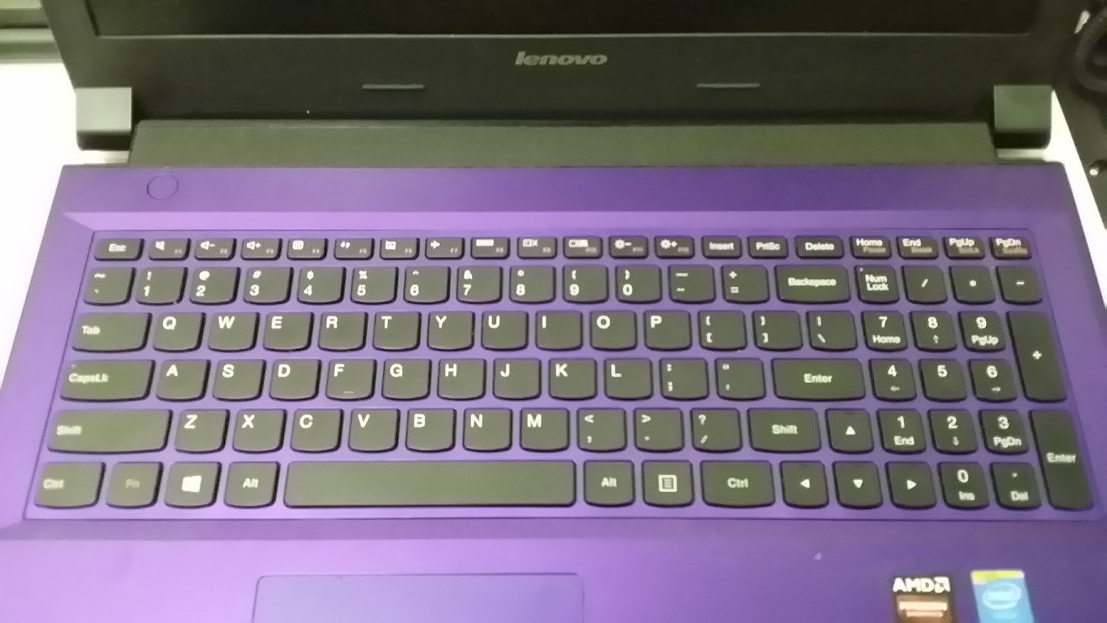
Now after removing the middle screw, I thought this is simple but to my surprise I need to flip over to remove the keyboard instead. Carefully I removed the entire keyboard panel as not to damaged the keyboard & touchpad ribbon cables.


Flipping over the keyboard panel after its been removed. Nothing much here but just to shows you how it looks like.


The below picture is the mainboard revealed, just like normal the HDD, battery and other stuffs is visible, but I can't seems to find the RAM's slot(s). Now it hits me again, the RAM slot(s) might be underneath the mainboard and just to be sure I need to remove the mainboard.... ugghhh !! This have disassembly tasks have become from normal to extreme. 


There are 6 screws to remove the battery, be careful on the connectors as its directly connected to the mainboard thus you need to tilt it up abit before sliding out.


How it looks after removing the battery.


Now to remove the HDD, you need to first disconnect the ribbon cable then only remove the 4 screws.


This is how it looks like after removing the HDD.


Before removing the mainboard, you will need to first disconnect all those ribbon cables (as shown below).


Now its time to remove the screws, location as show below. Take note that there's CMOS battery attached to the mainboard and need a little bit of prying on the battery as its glued to the case.


After removing the mainboard, this is how it looks like.


This is the mainboard's view.


Now flip it over, you now able to see the RAM's slots. There are 2 DIMMs available.


Upon checking the RAM's specification, its a DDR4-2400 type. Now I have compared it with HP's PartSurfer website (just for double confirmation). It shows SPS-MEM 4GB 2133MHz 1.2v DDR4 SHARED (P/N : 820569-005).


Sadly upon checking with Kingston & Transcend website, they no longer supports or manufacturer RAM upgrade for this model. Hence I will need to look for an almost similar specifications but un-tested for this notebook thus I'm also not sure of the stability of it.

I've yet to check with HP for the parts availability but I'm doubtful they will have it too. Its kinda sucks for this model to have 2 DIMMs slots yet we need to remove almost everything just for a RAM upgrade.

I still like those models where its just as simple as removing part of the bottom cover to reveal on the RAM or HDD parts. Well I think those days are gone now for sure.

!!! HAPPY COMPUTING !!!

Jul 27, 2018

Notebook - Samsung Keyboard Dock AA-RD7NMKD (Disassembly)

It's been sometime now since my last posting, it was due to my heavy workload at that time and coincides with the hand-over exercise to my replacement (I've moved to new company) :)

A friend of mine recently requested my help on checking his Samsung Tablet/Notebook (XE500T1C) and the Keyboard Dock (AA-RD7NMKD), he told me that the keyboard & the touchpad no longer works after an upgrade to Win8.1 version. Now based on my understanding that any OS upgrades will usually breaks the original drivers, however this was not the case even after I've reformatted it thus my troubleshooting went hardware side.

1) This is the how it looks like (before disassembly).


2) At the bottom, remove those "Rubbers Stand-Off" as circled in the picture.


3) After removing it will reveals the hidden screws as shown here.


4) After removing those hidden screws, you will need to "slowly peel-off" the cover, try not to breaks any of the inter-lock mechanism.
 
 
5) The inside view of keyboard docking unit.
 
 
Upon checking the hardware and cables, all components was in working condition. It seems nothing is wrong here but once I go in-depth diagnostics... I've found the I/O chip is faulty as shown below here.
 
 
With this chip malfunction, it have affected the following components :-
 
  • Keyboard
  • Touchpad
  • USB ports (all ports)
  • Lid Sensor
The only components that is still working is the charging module, due to lack of tools and resources to get a replacement chip, I was unable to repair/replace that faulty chip..... sadly.....
 
I've no choice but to inform my friend to either use an USB or Bluetooth Keyboard & Mouse for his daily use and since the tablet is still in good condition (albeit the faulty docking unit) he can still use the touchscreen and the stylus for his work.
 
Note : Always be extra cautious when performing disassembly of an aging notebooks/tablets etc. As over the time those covers, inter-locking mechanism, rubbers etc. will tends to break-off or cracks easily due to hardened & aging plastics.
 
 
!!! HAPPY COMPUTING !!!


Dec 8, 2015

Notebook - HP EliteBook Folio 9470m UltraBook (Disassembly)

This is just a references for disassembling the HP EliteBook Folio 9470m UltraBook model. You may not need to go to the extend of dismantling to the "bare" for common upgrades like RAM and HDD or mSSD, but just in case some genius out there decided to have a go (its not for faint hearted, be warned).

1. Push side way to remove the notebook's battery as shown below.

2. Remove the screws as shown to disclose the storage's bays (2 screws).


3. Once the cover is removed, it will reveal the storage bays which consist of 1 x mSSD slot and 1 x SATA HDD bay. Depending on the country of purchase, some models may comes with mSSD or HDD only or maybe both.

Note : Some model comes with mSSD Cache 32GB.

mSSD Location.

HDD Bay Location.

4. Remove the screws as shown to reveal the RAM slots and other components.


5. Once the cover is removed, you can now view the keyboard's screws as shown below (3 screws).


6. Once the keyboard's screws have been removed, turn over and slowly and very carefully to remove the keyboard. Please take note that the keyboard have an interlocking mechanism (or notches), so removing it must be very slow, careful and a steady hand.


Remarks : Becareful not to damage any connectors and its ribbon cables shown below, it will affects keyboard's functionalities.

Remarks : Below picture is the exact location of the keyboard's notches location.


7. Once the keyboard is removed, turn back to the bottom. Now proceed to remove all screws as shown, becareful of the screws length where some is shorter than the normal. A total of 19 screws.

Note : You need to peel off the CMOS battery which is sticked onto the chassis and ensure also the antenna cables is disconnected before removing the mid chassis.


8. Once the "Mid Panel" is removed, it will disclose the mainboard of the notebook. Proceed to disconnect all the connectors as shown below (4 Connectors).


9. Once all the connectors is disconnected, now we need to remove the mainboard's screws first as shown below (2 screws).


10. Once the mainboard's screws is removed, now we need to remove the "CPU's Fan" as shown below (1 screw) and its connector.


11. Now once the "CPU's Fan" is removed, we can proceed to remove the mainboard slowly. Note that it will be a bit tricky as the "Audio/Headphone" port is stuck in between the base chassis. The below picture shows that the mainboard removed.


12. The "LCD Screen" is still attached to the chassis, to remove it you must remove the screws as show below (4 screws). But take note before removing the screws you may need to slightly open the screen at 90 degrees angle for an easier approach.


13. Now the "LCD Screen" is separated from the base chassis. This is how it looks like once the screen is separated.


14. Now I'm not going to show how to remove the LCD screen as this will be quite easy to perform, but be aware of the "LCD's Inverter" board which might cause some electrical shock. Also a mishandling of the screen will rendered it either crack or malfunction.


Also since I've successfully dismantled the notebook, I've took the liberty to label most or commonly known parts as shown below.


Now I will not recommend this procedures unless really necessary and will definitely void all warranty that applies. So do this at your own risks.

Happy Computing !