1. Push side way to remove the notebook's battery as shown below.
2. Remove the screws as shown to disclose the storage's bays (2 screws).
3. Once the cover is removed, it will reveal the storage bays which consist of 1 x mSSD slot and 1 x SATA HDD bay. Depending on the country of purchase, some models may comes with mSSD or HDD only or maybe both.
Note : Some model comes with mSSD Cache 32GB.
 |
| mSSD Location. |
 |
| HDD Bay Location. |
4. Remove the screws as shown to reveal the RAM slots and other components.
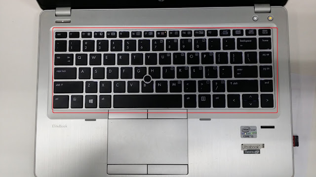
5. Once the cover is removed, you can now view the keyboard's screws as shown below (3 screws).
6. Once the keyboard's screws have been removed, turn over and slowly and very carefully to remove the keyboard. Please take note that the keyboard have an interlocking mechanism (or notches), so removing it must be very slow, careful and a steady hand.

Remarks : Becareful not to damage any connectors and its ribbon cables shown below, it will affects keyboard's functionalities.
Remarks : Below picture is the exact location of the keyboard's notches location.
7. Once the keyboard is removed, turn back to the bottom. Now proceed to remove all screws as shown, becareful of the screws length where some is shorter than the normal. A total of 19 screws.
Note : You need to peel off the CMOS battery which is sticked onto the chassis and ensure also the antenna cables is disconnected before removing the mid chassis.
8. Once the "Mid Panel" is removed, it will disclose the mainboard of the notebook. Proceed to disconnect all the connectors as shown below (4 Connectors).
9. Once all the connectors is disconnected, now we need to remove the mainboard's screws first as shown below (2 screws).
10. Once the mainboard's screws is removed, now we need to remove the "CPU's Fan" as shown below (1 screw) and its connector.
11. Now once the "CPU's Fan" is removed, we can proceed to remove the mainboard slowly. Note that it will be a bit tricky as the "Audio/Headphone" port is stuck in between the base chassis. The below picture shows that the mainboard removed.
12. The "LCD Screen" is still attached to the chassis, to remove it you must remove the screws as show below (4 screws). But take note before removing the screws you may need to slightly open the screen at 90 degrees angle for an easier approach.
13. Now the "LCD Screen" is separated from the base chassis. This is how it looks like once the screen is separated.
14. Now I'm not going to show how to remove the LCD screen as this will be quite easy to perform, but be aware of the "LCD's Inverter" board which might cause some electrical shock. Also a mishandling of the screen will rendered it either crack or malfunction.
Also since I've successfully dismantled the notebook, I've took the liberty to label most or commonly known parts as shown below.
Now I will not recommend this procedures unless really necessary and will definitely void all warranty that applies. So do this at your own risks.
Happy Computing !


No comments:
Post a Comment